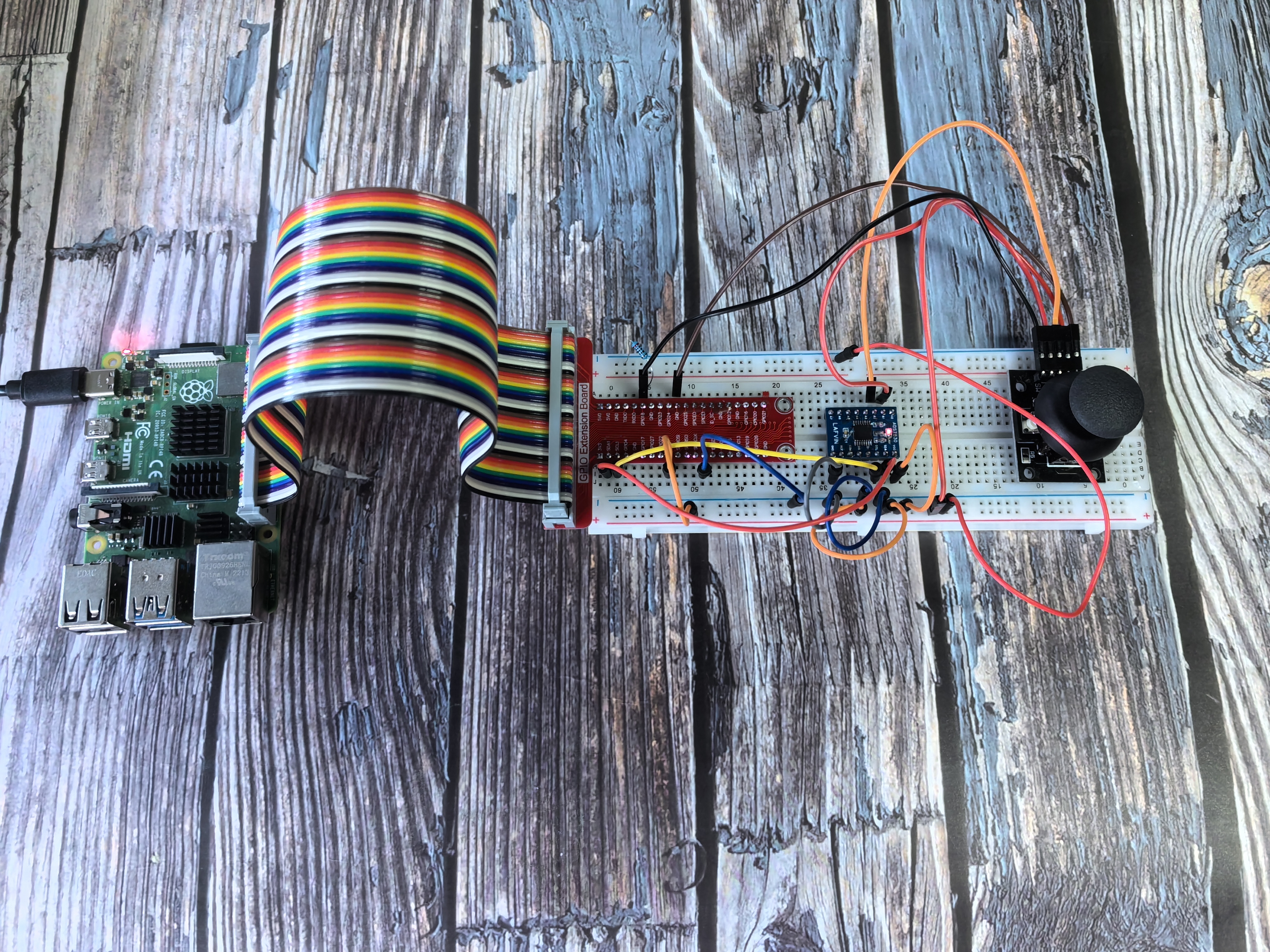
2.1.2 Joystick
Introduction
In this beginner-friendly project, you’ll learn how a joystick works by moving it around and seeing the results displayed on your screen. This will teach you about analog inputs and how to read position data.
Components
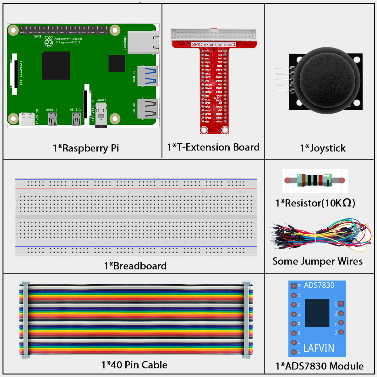
What is ADS7830?
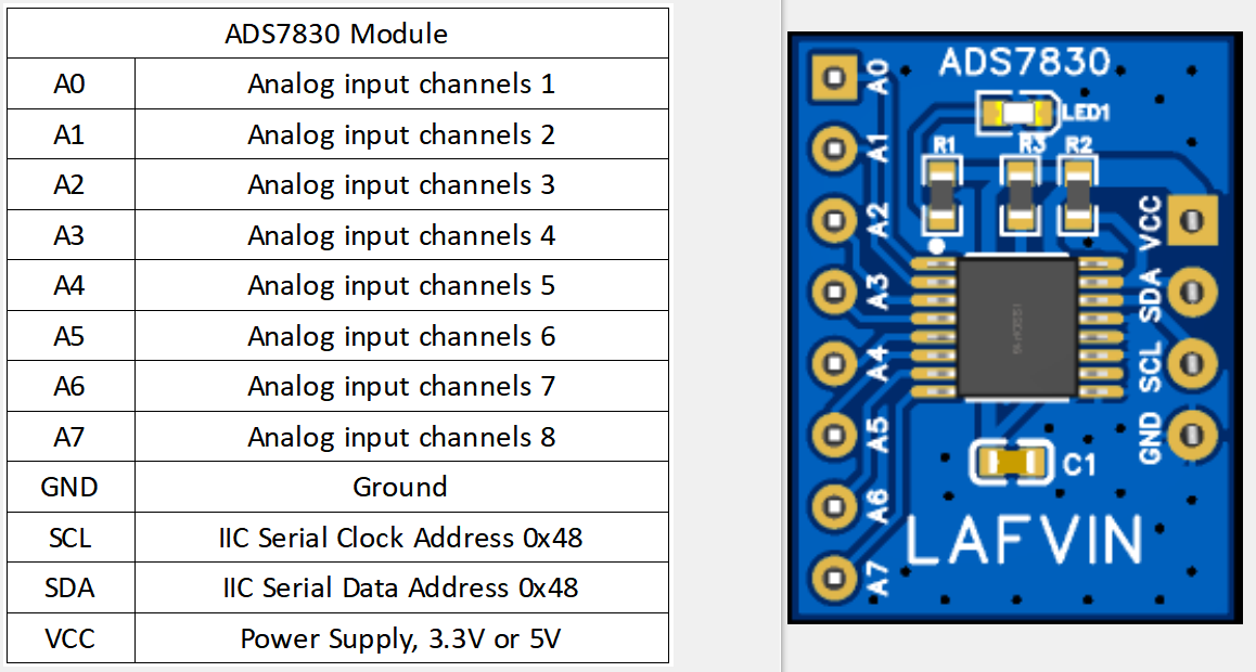
The ADS7830 is a special chip that helps your Raspberry Pi read analog signals. Think of it as a translator - it converts the continuous voltage signals from the joystick into digital numbers that your computer can understand.
Key features for beginners: - It can read 8 different analog inputs - It uses I2C communication (a simple 2-wire protocol) - It provides 8-bit resolution (values from 0 to 255)
Understanding ADC (Analog-to-Digital Converter)
What does ADC do? An ADC converts analog signals (like the smooth movement of a joystick) into digital numbers that computers can work with.
How does it work? Our ADC has 8-bit resolution, which means it can produce 256 different values (2^8 = 256). It takes the 3.3V input range and divides it into 256 equal parts:
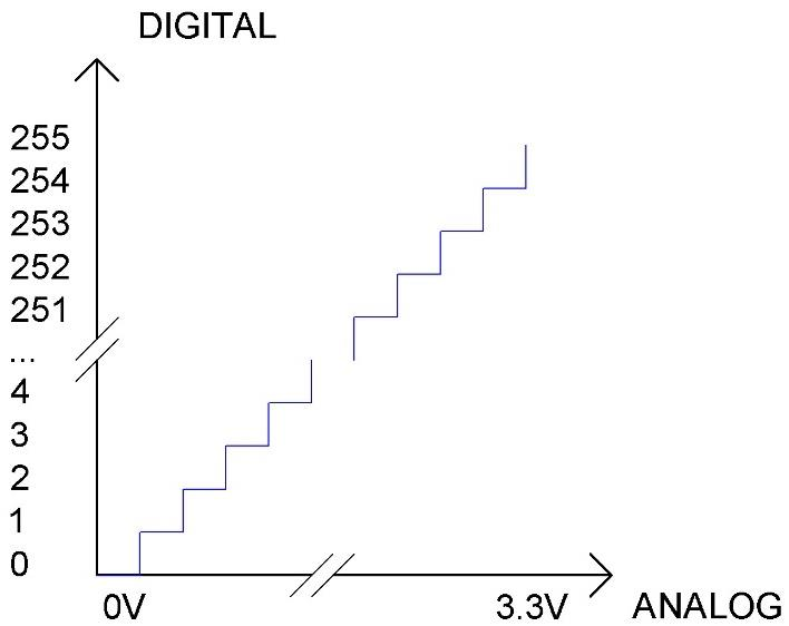
Simple breakdown: - Range 1: 0V to 3.3/256V = Digital value 0 - Range 2: 3.3/256V to 2×3.3/256V = Digital value 1 - Range 3: 2×3.3/256V to 3×3.3/256V = Digital value 2 - And so on…
Why does this matter? The more bits an ADC has, the more precise it becomes. With 8 bits, we get 256 different positions - that’s pretty good for detecting joystick movement!
What is a Joystick?
A joystick is like a mini steering wheel that can move in all directions. It translates the physical movement of a stick into electrical signals that your computer can read.
How does it work? - X-axis: Measures left-to-right movement - Y-axis: Measures up-and-down movement - Z-axis: Detects when you press the joystick down like a button
Think of it like a coordinate system in math class - any position can be described using X and Y coordinates!
The magic inside: The joystick uses two potentiometers (variable resistors) - one for each axis. As you move the stick, these potentiometers change their resistance, which changes the voltage output.
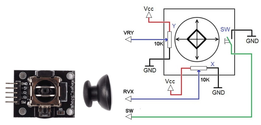
Reading Joystick Data - The Three Types:
X and Y-axis data: These are analog signals (smooth, continuous values) that need the ADS7830 to convert them to digital numbers
Z-axis data: This is a simple digital signal (pressed = 0, not pressed = 1) that can be read directly by a GPIO pin
Beginner tip: The joystick essentially gives you three pieces of information - where it’s pointing horizontally (X), where it’s pointing vertically (Y), and whether it’s being pressed down (Z)!
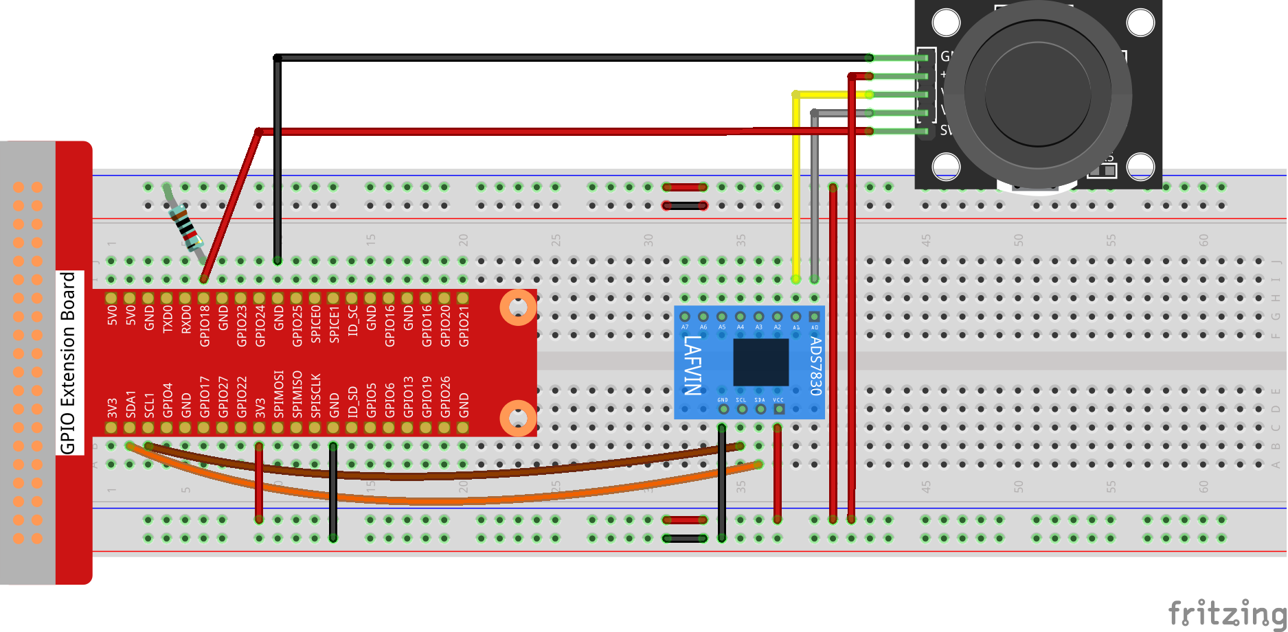
Connect
T-Board Name |
physical |
wiringPi |
BCM |
|---|---|---|---|
GPIO17 |
Pin 11 |
0 |
17 |
GPIO28 |
Pin 12 |
1 |
18 |
GPIO27 |
Pin 13 |
2 |
27 |
GPIO22 |
Pin 15 |
3 |
22 |
Code
For C Language User
Go to the code folder compile and run.
cd ~/super-starter-kit-for-raspberry-pi/c/2.1.2/
g++ 2.1.2_Joystick.cpp -I ../Lib/ADCDevice -L ../Lib/ADCDevice -lADCDevice -lwiringPi
sudo ./a.out
After the code runs, turn the Joystick, then the corresponding values of x, y, Btn are displayed on screen.
This is the complete code
#include <wiringPi.h>
#include <stdio.h>
#include <softPwm.h>
#include <ADCDevice.hpp>

#define Z_Pin 1     //define pin for axis Z

ADCDevice *adc;  // Define an ADC Device class object

int main(void){
    adc = new ADCDevice();
    printf("Program is starting ... \n");

    if(adc->detectI2C(0x48)){// Detect the ads7830
        delete adc;               // Free previously pointed memory
        adc = new ADS7830();      // If detected, create an instance of ADS7830.
    }
    else{
        printf("No correct I2C address found, \n"
        "Please use command 'i2cdetect -y 1' to check the I2C address! \n"
        "Program Exit. \n");
        return -1;
    }
    wiringPiSetup();
    pinMode(Z_Pin,INPUT);       //set Z_Pin as input pin and pull-up mode
    pullUpDnControl(Z_Pin,PUD_UP);
    while(1){
        int val_Z = digitalRead(Z_Pin);  //read digital value of axis Z
        int val_Y = adc->analogRead(0);      //read analog value of axis X and Y
        int val_X = adc->analogRead(1);
        printf("val_X: %d  ,\tval_Y: %d  ,\tval_Z: %d \n",val_X,val_Y,val_Z);
        delay(100);
    }
    return 0;
}
For Python Language User
Go to the code folder and run.
cd ~/super-starter-kit-for-raspberry-pi/python
python 2.1.2_Joystick.py
After the code runs, turn the Joystick, then the corresponding values of x, y, Btn are displayed on screen.
This is the complete code
#!/usr/bin/env python3

import RPi.GPIO as GPIO
import time
from ADCDevice import *

Z_Pin = 12      # define Z_Pin
adc = ADCDevice() # Define an ADCDevice class object

def setup():
    global adc
    if(adc.detectI2C(0x48)): # Detect the ads7830
        adc = ADS7830()
    else:
        print("No correct I2C address found, \n"
        "Please use command 'i2cdetect -y 1' to check the I2C address! \n"
        "Program Exit. \n");
        exit(-1)
    GPIO.setmode(GPIO.BOARD)
    GPIO.setup(Z_Pin,GPIO.IN,GPIO.PUD_UP)   # set Z_Pin to pull-up mode
def loop():
    while True:
        val_Z = GPIO.input(Z_Pin)       # read digital value of axis Z
        val_Y = adc.analogRead(0)           # read analog value of axis X and Y
        val_X = adc.analogRead(1)
        print ('value_X: %d ,\tvlue_Y: %d ,\tvalue_Z: %d'%(val_X,val_Y,val_Z))
        time.sleep(0.01)

def destroy():
    adc.close()
    GPIO.cleanup()

if __name__ == '__main__':
    print ('Program is starting ... ') # Program entrance
    setup()
    try:
        loop()
    except KeyboardInterrupt: # Press ctrl-c to end the program.
        destroy()
Phenomenon