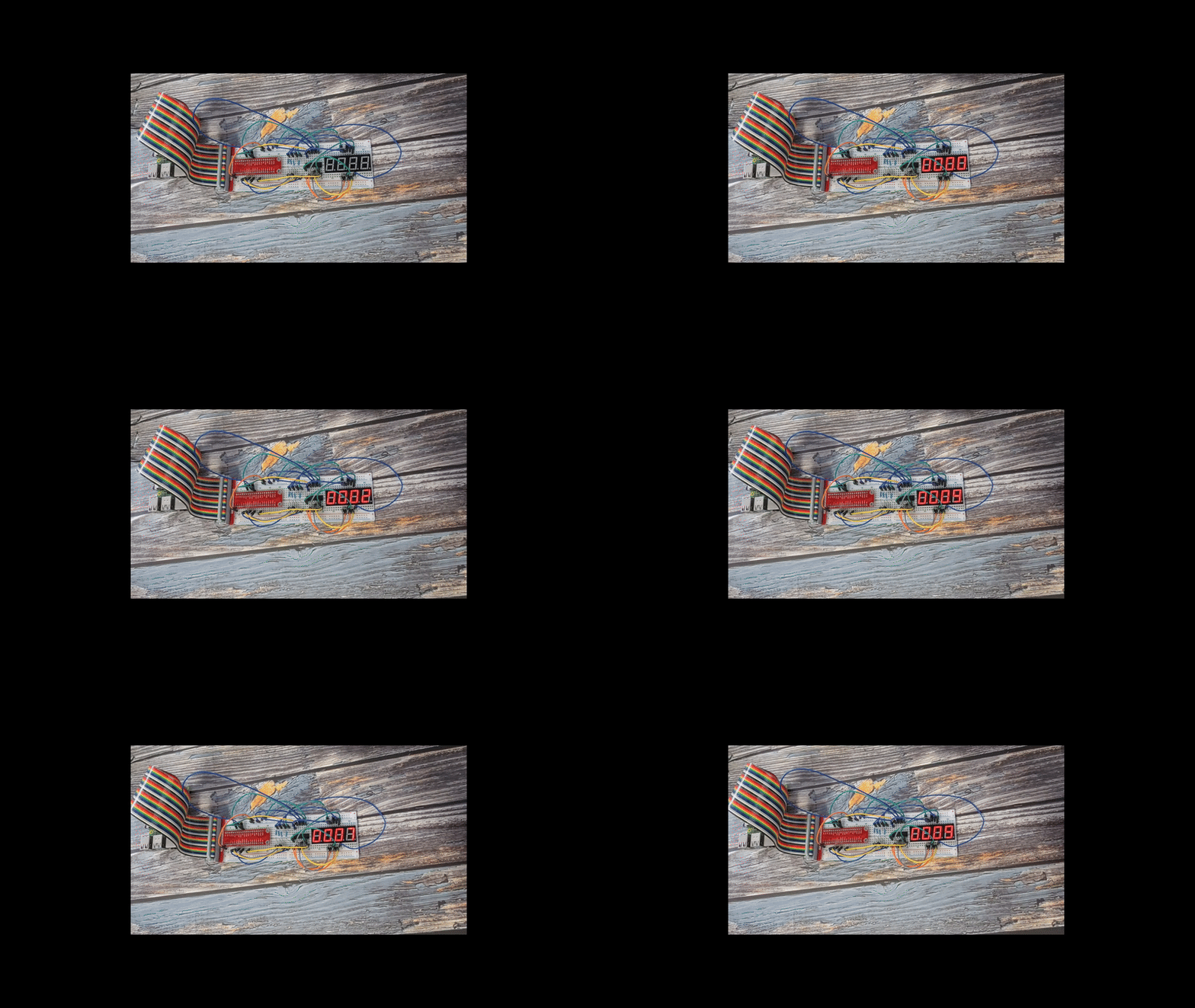
1.1.5 4-Digit 7-Segment Display
Introduction
In this project, we’ll learn how to control a 4-digit 7-segment display to show numbers and create a simple counter.
Components
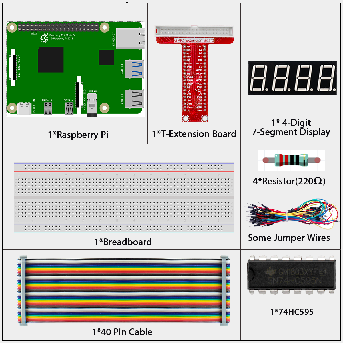
4-Digit 7-Segment Display
A 4-digit 7-segment display combines four individual 7-segment displays in one package, allowing us to show numbers up to 4 digits.
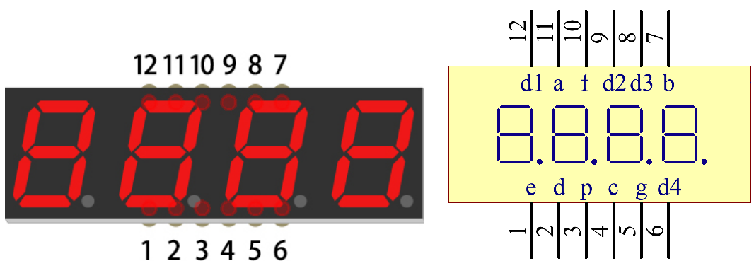
How It Works: Multiplexing
This display uses a technique called multiplexing to show all four digits with minimal connections:
Only one digit is actually illuminated at any given moment
The display rapidly cycles through each digit (typically switching every 5ms)
Due to persistence of vision (how our eyes retain an image briefly), we perceive all four digits as continuously lit
For example, to display “1234”: - First, we activate digit 1 and show “1” - Then quickly switch to digit 2 and show “2” - Then digit 3 showing “3” - Then digit 4 showing “4” - Repeat this cycle rapidly (200+ times per second)
This cycling happens so fast that our eyes see all four digits simultaneously.
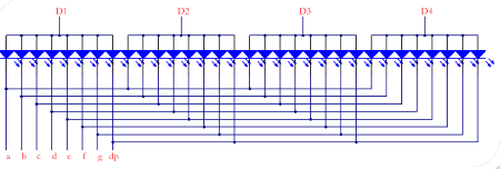
Display Codes
Each digit uses the same segment patterns as the single 7-segment display:
Number |
Binary Pattern (dp)gfedcba |
Hex Code |
Segments Lit |
|---|---|---|---|
0 |
00111111 |
0x3F |
a, b, c, d, e, f |
1 |
00000110 |
0x06 |
b, c |
2 |
01011011 |
0x5B |
a, b, d, e, g |
3 |
01001111 |
0x4F |
a, b, c, d, g |
4 |
01100110 |
0x66 |
b, c, f, g |
5 |
01101101 |
0x6D |
a, c, d, f, g |
6 |
01111101 |
0x7D |
a, c, d, e, f, g |
7 |
00000111 |
0x07 |
a, b, c |
8 |
01111111 |
0x7F |
a, b, c, d, e, f, g |
9 |
01101111 |
0x6F |
a, b, c, d, f, g |
A |
01110111 |
0x77 |
a, b, c, e, f, g |
B |
01111100 |
0x7C |
c, d, e, f, g |
C |
00111001 |
0x39 |
a, d, e, f |
D |
01011110 |
0x5E |
b, c, d, e, g |
E |
01111001 |
0x79 |
a, d, e, f, g |
F |
01110001 |
0x71 |
a, e, f, g |
Connect
T-Board Name |
physical |
wiringPi |
BCM |
|---|---|---|---|
GPIO17 |
Pin 11 |
0 |
17 |
GPIO27 |
Pin 13 |
2 |
27 |
GPIO22 |
Pin 15 |
3 |
22 |
SPIMOSI |
Pin 19 |
12 |
10 |
GPIO18 |
Pin 12 |
1 |
18 |
GPIO23 |
Pin 16 |
4 |
23 |
GPIO24 |
Pin 18 |
5 |
24 |

How the Circuit Works:
The 74HC595 shift register controls which segments are lit
The Raspberry Pi directly controls which digit is active at any moment
By rapidly switching between digits and changing segment patterns, we can display different numbers on each digit
Code
For C Language User
Go to the code folder compile and run.
cd ~/davinci-kit-for-raspberry-pi/c/1.1.5/
gcc 1.1.5_4-Digit.c -lwiringPi
sudo ./a.out
This is the complete code
#include <wiringPi.h>
#include <stdio.h>
#include <wiringShift.h>
#include <signal.h>
#include <unistd.h>

#define SDI 5
#define RCLK 4
#define SRCLK 1

const int placePin[] = {12, 3, 2, 0};
unsigned char number[] = {0x3f, 0x06, 0x5b, 0x4f, 0x66, 0x6d, 0x7d, 0x07, 0x7f, 0x6f};

int counter = 0;

void pickDigit(int digit)
{
    for (int i = 0; i < 4; i++)
    {
        digitalWrite(placePin[i], 1);
    }
    digitalWrite(placePin[digit], 0);
}

void hc595_shift(int8_t data)
{
    int i;
    for (i = 0; i < 8; i++)
    {
        digitalWrite(SDI, 0x80 & (data << i));
        digitalWrite(SRCLK, 1);
        delayMicroseconds(1);
        digitalWrite(SRCLK, 0);
    }
    digitalWrite(RCLK, 1);
    delayMicroseconds(1);
    digitalWrite(RCLK, 0);
}

void clearDisplay()
{
    int i;
    for (i = 0; i < 8; i++)
    {
        digitalWrite(SDI, 0);
        digitalWrite(SRCLK, 1);
        delayMicroseconds(1);
        digitalWrite(SRCLK, 0);
    }
    digitalWrite(RCLK, 1);
    delayMicroseconds(1);
    digitalWrite(RCLK, 0);
}

void loop()
{
    while(1){
    clearDisplay();
    pickDigit(0);
    hc595_shift(number[counter % 10]);

    clearDisplay();
    pickDigit(1);
    hc595_shift(number[counter % 100 / 10]);

    clearDisplay();
    pickDigit(2);
    hc595_shift(number[counter % 1000 / 100]);

    clearDisplay();
    pickDigit(3);
    hc595_shift(number[counter % 10000 / 1000]);
    }
}

void timer(int timer1)
{
    if (timer1 == SIGALRM)
    {
        counter++;
        alarm(1);
        printf("%d\n", counter);
    }
}

void main(void)
{
    if (wiringPiSetup() == -1)
    {
        printf("setup wiringPi failed !");
        return;
    }
    pinMode(SDI, OUTPUT);
    pinMode(RCLK, OUTPUT);
    pinMode(SRCLK, OUTPUT);

    for (int i = 0; i < 4; i++)
    {
        pinMode(placePin[i], OUTPUT);
        digitalWrite(placePin[i], HIGH);
    }
    signal(SIGALRM, timer);
    alarm(1);
    loop();
}
For Python Language User
Go to the code folder and run.
cd ~/super-starter-kit-for-raspberry-pi/python
python 1.1.5_4-Digit.py
This is the complete code
#!/usr/bin/env python3

 import RPi.GPIO as GPIO
 import time
 import threading

 # Pin definitions for the 74HC595 shift register
 SDI_PIN = 24     # Serial Data Input (DS)
 RCLK_PIN = 23    # Storage Register Clock (STCP)
 SRCLK_PIN = 18   # Shift Register Clock (SHCP)

 # Pins for selecting one of the four digits on the 4-digit display
 DIGIT_PINS = [10, 22, 27, 17]
 NUM_OF_DIGITS = len(DIGIT_PINS)

 # Common-anode 7-segment display codes for digits 0-9
 SEGMENT_CODES = [0x3f, 0x06, 0x5b, 0x4f, 0x66, 0x6d, 0x7d, 0x07, 0x7f, 0x6f]

 # Volatile counter updated by the timer interrupt
 counter = 0
 timer1 = None

 def writeToShiftRegister(data):
     """
     Sends a byte to the 74HC595 shift register.
     Parameters: data - The 8-bit data to send.
     """
     for i in range(8):
         GPIO.output(SDI_PIN, 0x80 & (data << i))
         GPIO.output(SRCLK_PIN, GPIO.HIGH)
         time.sleep(0.0001)
         GPIO.output(SRCLK_PIN, GPIO.LOW)

     GPIO.output(RCLK_PIN, GPIO.HIGH)
     time.sleep(0.0001)
     GPIO.output(RCLK_PIN, GPIO.LOW)

 def selectDigit(digitIndex):
     """
     Selects which of the 4 digits to activate.
     Parameters: digitIndex - The index of the digit to activate (0-3).
     """
     # Deactivate all digits first
     for i in range(NUM_OF_DIGITS):
         GPIO.output(DIGIT_PINS[i], GPIO.HIGH)

     # Activate the selected digit by setting its pin to LOW
     if 0 <= digitIndex < NUM_OF_DIGITS:
         GPIO.output(DIGIT_PINS[digitIndex], GPIO.LOW)

 def displayNumber():
     """
     Displays a single number on a single digit.
     This function is called rapidly for each digit to create the illusion of a solid number.
     """
     digits = [0] * NUM_OF_DIGITS
     tempCounter = counter

     # Extract each digit from the counter
     digits[0] = tempCounter % 10
     digits[1] = (tempCounter // 10) % 10
     digits[2] = (tempCounter // 100) % 10
     digits[3] = (tempCounter // 1000) % 10

     # Rapidly cycle through each digit, displaying its corresponding number
     for i in range(NUM_OF_DIGITS):
         for j in range(NUM_OF_DIGITS):
             GPIO.output(DIGIT_PINS[j], GPIO.HIGH)

         writeToShiftRegister(SEGMENT_CODES[digits[i]])
         GPIO.output(DIGIT_PINS[i], GPIO.LOW)

         time.sleep(0.0025)

 def timerHandler():
     """
     Timer handler function. Increments the counter every second.
     """
     global counter, timer1

     counter += 1
     print(f"Counter: {counter}")

     # Reschedule the timer for 1 second later
     timer1 = threading.Timer(1.0, timerHandler)
     timer1.start()

 def setup():
     """
     Initializes hardware, sets up GPIOs and the timer interrupt.
     Returns: 0 on success, 1 on failure.
     """
     global timer1

     try:
         GPIO.setmode(GPIO.BCM)
         GPIO.setwarnings(False)

         # Setup shift register pins
         GPIO.setup(SDI_PIN, GPIO.OUT, initial=GPIO.LOW)
         GPIO.setup(RCLK_PIN, GPIO.OUT, initial=GPIO.LOW)
         GPIO.setup(SRCLK_PIN, GPIO.OUT, initial=GPIO.LOW)

         # Setup digit selection pins
         for i in range(NUM_OF_DIGITS):
             GPIO.setup(DIGIT_PINS[i], GPIO.OUT, initial=GPIO.HIGH)  # Deactivate all digits initially

         # Setup the timer interrupt
         timer1 = threading.Timer(1.0, timerHandler)
         timer1.start()

         print("GPIO and timer setup successful!")
         return 0

     except Exception as e:
         print(f"Failed to setup hardware: {e}")
         return 1

 def destroy():
     """
     Clean up function for GPIO resources and timer.
     """
     global timer1

     if timer1:
         timer1.cancel()  # Cancel the timer

     GPIO.cleanup()
     print("GPIO cleanup and timer cancelled")

 def main():
     """
     Main function.
     Returns: Integer status code. 0 for success, 1 for error.
     """
     # Initialize the hardware
     if setup() != 0:
         return 1  # Exit if setup fails

     try:
         # Main loop for display multiplexing
         while True:
             displayNumber()
     except KeyboardInterrupt:
         print("\nProgram interrupted by user")
         destroy()
         return 0
     except Exception as e:
         print(f"An error occurred: {e}")
         destroy()
         return 1

 # If run this script directly, do:
 if __name__ == '__main__':
     main()
Phenomenon