1.1.6 I2C LCD1602
Introduction
The LCD1602 is a versatile character display that shows 32 characters arranged in 2 rows of 16 characters each. In this project, we’ll use an I2C-enabled LCD1602, which simplifies connections and saves GPIO pins on your Raspberry Pi.
Components

I2C LCD1602 Module
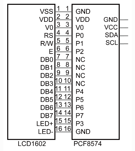
The I2C LCD1602 combines a standard 16×2 character LCD with an I2C interface adapter, requiring only 4 pins for connection:
GND: Ground connection
VCC: Power supply (5V)
SDA: Serial Data line for I2C communication
SCL: Serial Clock line for I2C communication
Why Use I2C?
A standard LCD1602 requires at least 6 GPIO pins to operate. The I2C adapter module solves this problem by:
Reducing connection pins from 6+ to just 4
Freeing up GPIO pins for other components
Simplifying the wiring process
The adapter uses a PCF8574 I2C chip that converts serial data from the Raspberry Pi into the parallel data format needed by the LCD.
I2C Address Settings
The default I2C address for the module is 0x27, though some modules may use 0x3F.
You can customize the address by modifying the A0/A1/A2 jumper pads on the back of the module: - Default state: A0=1, A1=1, A2=1 (address 0x27) - Shorting a pad changes its value to 0, modifying the address
Display Adjustments
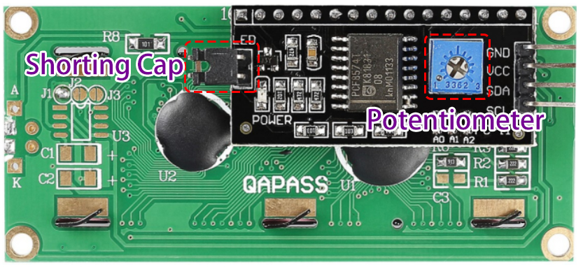
Contrast Adjustment: The blue potentiometer controls text visibility - Clockwise rotation: Increases contrast (darker text) - Counter-clockwise: Decreases contrast (lighter text)
Connect
The I2C connection requires only 4 wires:
LCD1602 Pin |
Raspberry Pi Pin |
Function |
|---|---|---|
GND |
Any GND |
Ground connection |
VCC |
5V |
Power supply |
SDA |
Pin 3 (GPIO2, SDA) |
I2C Serial Data |
SCL |
Pin 5 (GPIO3, SCL) |
I2C Serial Clock |
Note
Before using I2C devices, make sure I2C is enabled on your Raspberry Pi. You can check the appendix section for I2C configuration instructions.

Code
For C Language User
Running the Example Code
Follow these steps to compile and run the LCD1602 example:
Navigate to the code directory:
cd ~/super-starter-kit-for-raspberry-pi/c/1.1.6/
Compile the code (linking the wiringPi library):
gcc 1.1.6_Lcd1602.c -lwiringPi
Run the program (requires sudo for hardware access):
sudo ./a.out
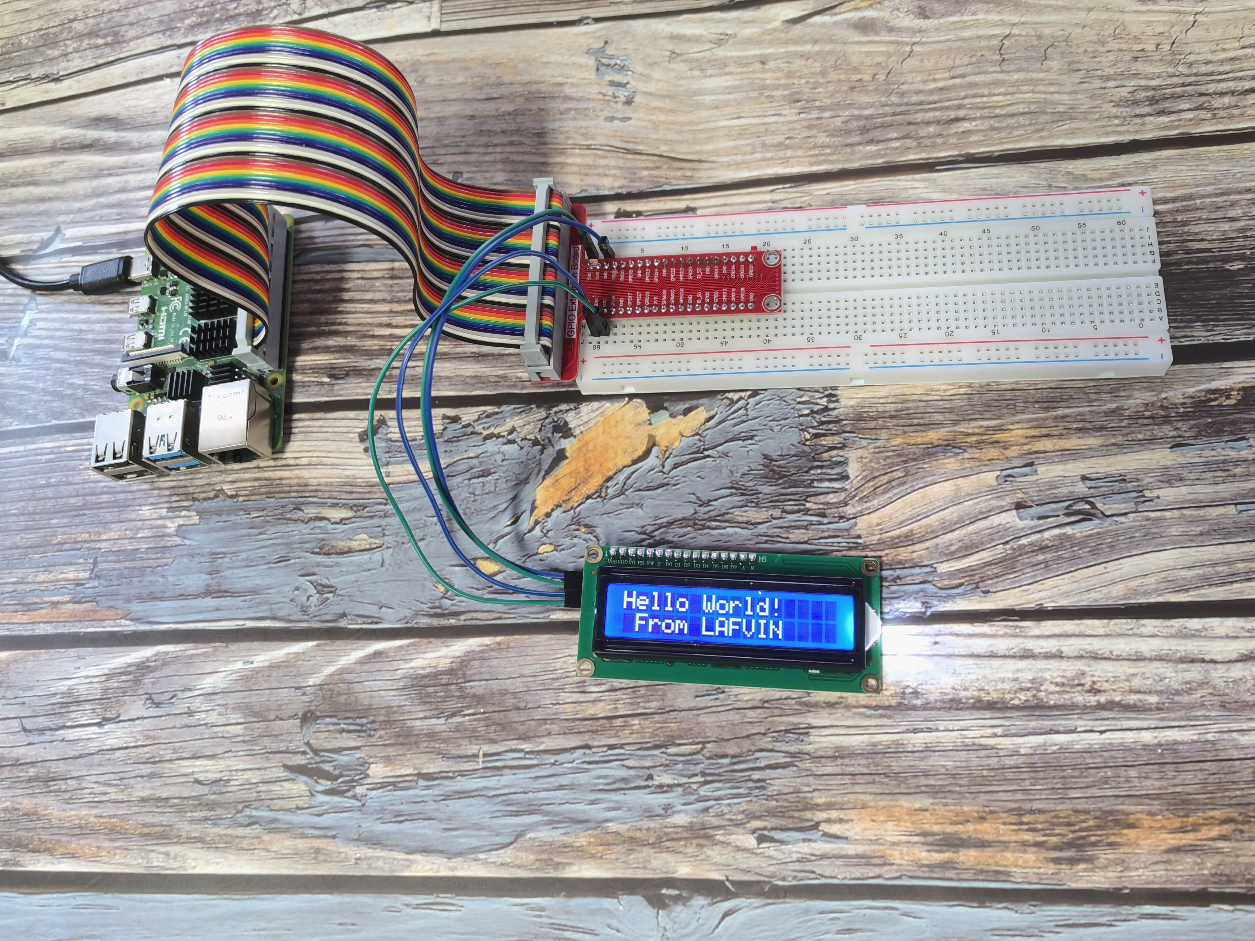
When the program runs successfully, you’ll see “Hello World!” on the first line and “From LAFVIN” on the second line of the LCD display.
Understanding the I2C LCD Code
The C code below provides a well-structured interface for controlling the LCD1602 through I2C communication. This implementation uses modern programming practices with clear function names, documentation, and error handling.
Key Components:
Constants: Defines important values like I2C address and LCD commands
Function Prototypes: Declares all functions at the beginning for better organization
Documentation: Uses Doxygen-style comments to explain function parameters and behavior
Key Functions:
lcd_init(): Sets up the I2C connection and initializes the LCD in 4-bit mode
lcd_write_byte(): Sends a byte to the LCD with the appropriate mode (command or data)
lcd_toggle_enable(): Pulses the Enable pin to latch data into the LCD
lcd_print_at(): Positions the cursor and displays text at that location
LCD Commands Used: - 0x01: Clear display - 0x0C: Display on, cursor off, no blink - 0x28: 2 lines, 5x7 dot matrix - 0x06: Entry mode - cursor moves right
Complete Code:
#include <stdio.h>
#include <stdlib.h> // Required for exit()
#include <string.h>
#include <wiringPi.h>
#include <wiringPiI2C.h>

// --- Constants ---

// I2C Address of the PCF8574A chip on the LCD's I2C backpack.
#define I2C_ADDR   0x27

// LCD Command and Character constants.
#define LCD_CHR  1 // Mode: Sending data (characters)
#define LCD_CMD  0 // Mode: Sending command

// LCD Line addresses.
#define LINE1  0x80 // Address for the 1st line.
#define LINE2  0xC0 // Address for the 2nd line.

// Bitmask for the backlight. On: 0x08, Off: 0x00.
#define LCD_BACKLIGHT 0x08

// Enable bit.
#define ENABLE 0x04

// --- Function Prototypes ---
void lcd_init(int* fd_ptr);
void lcd_write_byte(int fd, int bits, int mode);
void lcd_toggle_enable(int fd, int bits);
void lcd_clear(int fd);
void lcd_set_cursor(int fd, int col, int row);
void lcd_print(int fd, const char* message);
void lcd_print_at(int fd, int col, int row, const char* message);

/**
* @brief Toggles the Enable (EN) pin to latch data into the LCD.
* @param fd File descriptor for the I2C device.
* @param bits The data packet to send.
*/
void lcd_toggle_enable(int fd, int bits) {
    delayMicroseconds(500);
    wiringPiI2CWrite(fd, (bits | ENABLE));
    delayMicroseconds(500);
    wiringPiI2CWrite(fd, (bits & ~ENABLE));
    delayMicroseconds(500);
}

/**
* @brief Writes a single byte to the LCD in 4-bit mode.
* @param fd File descriptor for the I2C device.
* @param bits The byte to write.
* @param mode LCD_CMD for commands, LCD_CHR for data.
*/
void lcd_write_byte(int fd, int bits, int mode) {
    // Send the high nibble (4 bits).
    int bits_high = mode | (bits & 0xF0) | LCD_BACKLIGHT;
    wiringPiI2CWrite(fd, bits_high);
    lcd_toggle_enable(fd, bits_high);

    // Send the low nibble (4 bits).
    int bits_low = mode | ((bits << 4) & 0xF0) | LCD_BACKLIGHT;
    wiringPiI2CWrite(fd, bits_low);
    lcd_toggle_enable(fd, bits_low);
}

/**
* @brief Initializes the LCD display in 4-bit mode.
* @param fd_ptr Pointer to an integer where the file descriptor will be stored.
*/
void lcd_init(int* fd_ptr) {
    *fd_ptr = wiringPiI2CSetup(I2C_ADDR);
    if (*fd_ptr == -1) {
        printf("Failed to initialize I2C device with address %d.\n", I2C_ADDR);
        exit(1);
    }

    // Initialization sequence for 4-bit mode.
    lcd_write_byte(*fd_ptr, 0x33, LCD_CMD); // Must be sent to ensure 8-bit mode for init
    lcd_write_byte(*fd_ptr, 0x32, LCD_CMD); // Now set to 4-bit mode
    lcd_write_byte(*fd_ptr, 0x06, LCD_CMD); // Entry mode: cursor moves to the right
    lcd_write_byte(*fd_ptr, 0x0C, LCD_CMD); // Display control: display on, cursor off, no blink
    lcd_write_byte(*fd_ptr, 0x28, LCD_CMD); // Function set: 2 lines, 5x8 dots
    lcd_write_byte(*fd_ptr, 0x01, LCD_CMD); // Clear display
    delay(1);
}

/**
* @brief Clears the LCD screen and returns the cursor to home.
* @param fd File descriptor for the I2C device.
*/
void lcd_clear(int fd) {
    lcd_write_byte(fd, 0x01, LCD_CMD); // Clear display command
    delay(1);
}

/**
* @brief Positions the cursor at a specified column and row.
* @param fd File descriptor for the I2C device.
* @param col The column (0-15).
* @param row The row (0-1).
*/
void lcd_set_cursor(int fd, int col, int row) {
    if (row == 0) {
        lcd_write_byte(fd, LINE1 + col, LCD_CMD);
    } else {
        lcd_write_byte(fd, LINE2 + col, LCD_CMD);
    }
}

/**
* @brief Prints a string to the LCD at the current cursor position.
* @param fd File descriptor for the I2C device.
* @param message The string to print.
*/
void lcd_print(int fd, const char* message) {
    while (*message) {
        lcd_write_byte(fd, *message++, LCD_CHR);
    }
}

/**
* @brief A utility function to set the cursor and print a string.
* @param fd File descriptor for the I2C device.
* @param col The column (0-15).
* @param row The row (0-1).
* @param message The string to print.
*/
void lcd_print_at(int fd, int col, int row, const char* message) {
    lcd_set_cursor(fd, col, row);
    lcd_print(fd, message);
}

/**
* @brief Main function.
* @return 0 on success, 1 on failure.
*/
int main(void) {
    int lcd_fd;

    // wiringPiSetup is essential for delay functions and I2C.
    if (wiringPiSetup() == -1) {
        printf("wiringPiSetup failed!\n");
        return 1;
    }

    lcd_init(&lcd_fd);

    lcd_print_at(lcd_fd, 0, 0, "Hello World!");
    lcd_print_at(lcd_fd, 1, 1, "From LAFVIN");

    return 0;
}
For Python Language User
Running the Python Example
Follow these steps to run the Python version of the LCD1602 example:
Navigate to the Python code directory:
cd ~/super-starter-kit-for-raspberry-pi/python
Run the Python script (requires sudo for hardware access):
sudo python 1.1.6_Lcd1602.py
Understanding the Python Code
#!/usr/bin/env python3

 import LCD1602
 import time

 def setup():
     """
     Initialize the LCD1602 display with I2C address and backlight settings.
     Returns: 0 on success, 1 on failure.
     """
     try:
         LCD1602.init(0x27, 1)  # init(slave address, background light)
         print("LCD1602 initialized successfully!")
         return 0
     except Exception as e:
         print(f"Failed to initialize LCD1602: {e}")
         return 1

 def display_static_message():
     """Display static welcome messages on the LCD."""
     LCD1602.write(0, 0, 'Hello World!')
     LCD1602.write(1, 1, 'From LAFVIN')
     time.sleep(2)

 def destroy():
     """Clean up the LCD display."""
     try:
         LCD1602.clear()
         print("LCD cleared and cleaned up")
     except Exception as e:
         print(f"Error during cleanup: {e}")

 def main():
     """
     Main function - simple LCD display.
     Returns: Integer status code. 0 for success, 1 for error.
     """
     # Initialize the LCD
     if setup() != 0:
         return 1

     try:
         # Display welcome message
         display_static_message()
         print("Message displayed on LCD successfully!")
         return 0

     except KeyboardInterrupt:
         print("\nProgram interrupted by user")
         destroy()
         return 0
     except Exception as e:
         print(f"An error occurred: {e}")
         destroy()
         return 1

 if __name__ == "__main__":
     main()
Code Structure Explained
The Python code above demonstrates a well-structured approach to working with the LCD1602:
Modular Design: The code is organized into separate functions for initialization, display, and cleanup
Error Handling: Comprehensive try/except blocks catch and report potential issues
Documentation: Each function includes docstrings explaining its purpose and return values
Clean Exit: The destroy() function ensures proper cleanup when the program terminates
Key Functions:
setup(): Initializes the LCD with address 0x27 and enables the backlight
display_static_message(): Shows “Hello World!” and “From LAFVIN” on the display
destroy(): Properly clears the display during shutdown
main(): Orchestrates the program flow and handles errors
When running successfully, you’ll see the text displayed on your LCD screen, and the program will provide informative status messages in the terminal.
Phenomenon
Below is what you should see on your LCD1602 display: