1.3.4 Relay
Introduction
In this project, we’ll learn how to use a relay - an electronic switch that lets your Raspberry Pi safely control high-power devices like lamps, fans, or other household appliances.
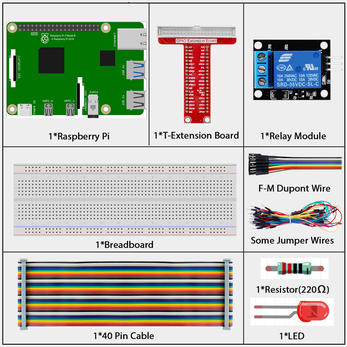
Components
What is a Relay?
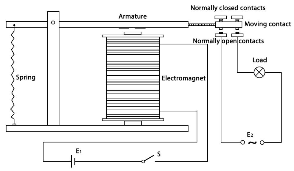
A relay is like a switch that’s controlled by electricity instead of your finger. It has two separate circuits: - A low-power control circuit (connected to your Raspberry Pi) - A high-power load circuit (for the device you want to control)
This separation is important because it keeps your Raspberry Pi safe while letting you control powerful devices.
Why Use a Relay?
Relays are perfect when you need to: - Control high-voltage devices (like 120V/240V home appliances) with your low-voltage Raspberry Pi - Switch devices that need more current than your Pi can provide - Isolate your Pi from potentially dangerous voltages - Turn household devices on and off automatically
Our Relay Module
The relay module in this kit is ready to use with your Raspberry Pi: - It includes all necessary components (resistors, diodes, and transistors) - It can be connected directly to your Raspberry Pi without extra components - It has clear markings for all connections - It includes an indicator LED that shows when the relay is activated
How a Relay Works - The Simple Version
Inside every relay is an electromagnet that controls a mechanical switch:
When you send a signal from your Raspberry Pi, the electromagnet is activated
The electromagnet pulls a metal arm (the armature) toward it
This movement connects or disconnects the electrical contacts
When the signal stops, a spring pulls the arm back to its original position
The Relay’s Two States
A relay has two possible contact states:
Normally Open (NO): The circuit is disconnected when the relay is off (like a light switch in the off position)
Normally Closed (NC): The circuit is connected when the relay is off
When you activate the relay, these states flip - NO contacts close and NC contacts open.
Safety First!
Warning
When working with relays that control household power (120V/240V): - NEVER touch the high-voltage terminals when power is connected - Make sure all high-voltage wiring is properly insulated - If you’re not experienced with electrical work, ask for help from someone who is
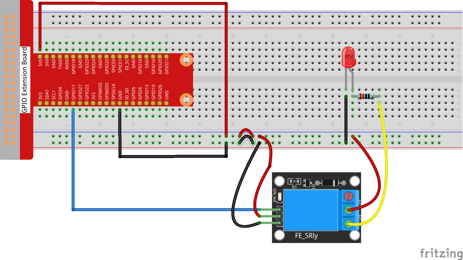
Connect
Code
For C Language User
Go to the code folder compile and run.
cd ~/super-starter-kit-for-raspberry-pie/c/1.3.4
gcc 1.3.4_Relay.c -lwiringPi
sudo ./a.out
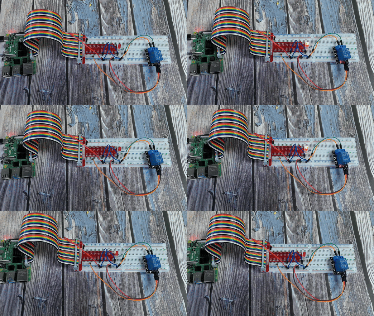
After the code runs, the LED will light up. In addition, you can hear a ticktock caused by breaking normally close contact and closing normally open contact.
This is the complete code
#include <wiringPi.h>
#include <stdio.h>
#include <stdlib.h> // Required for exit()

// Define the GPIO pin connected to the relay module.
#define RELAY_PIN 0

// Define the interval for switching the relay state in milliseconds.
#define SWITCH_INTERVAL_MS 1000

/**
* @brief Initializes wiringPi and configures the relay pin as an output.
*/
void setup_relay() {
    if (wiringPiSetup() == -1) {
        printf("Failed to setup wiringPi!\n");
        exit(1);
    }
    pinMode(RELAY_PIN, OUTPUT);
}

/**
* @brief Main application loop to toggle the relay.
*/
void relay_toggle_loop() {
    while (1) {
        // Close the relay circuit (often by pulling the pin LOW).
        // This might turn an external device (like an LED) ON.
        printf("Relay CLOSED (circuit complete).\n");
        digitalWrite(RELAY_PIN, LOW);
        delay(SWITCH_INTERVAL_MS);

        // Open the relay circuit (by pulling the pin HIGH).
        // This will turn the external device OFF.
        printf("Relay OPEN (circuit broken).\n");
        digitalWrite(RELAY_PIN, HIGH);
        delay(SWITCH_INTERVAL_MS);
    }
}

/**
* @brief Main function.
* @return Integer status code.
*/
int main(void) {
    setup_relay();
    relay_toggle_loop();
    return 0; // Unreachable code.
}
For Python Language User
Go to the code folder and run.
cd ~/super-starter-kit-for-raspberry-pi/python
python 1.3.4_Relay.py
After the code runs, the LED will light up. In addition, you can hear a ticktock caused by breaking normally close contact and closing normally open contact.
This is the complete code
#!/usr/bin/env python3
"""
Relay Module Control - Python version matching C implementation

This implementation replicates the C code's features:
1. Professional function separation and naming
2. Clear relay state descriptions (CLOSED/OPEN)
3. Proper constant definitions
4. Enhanced error handling and status codes
"""

import RPi.GPIO as GPIO
import time
import sys

# Define the GPIO pin connected to the relay module
RELAY_PIN = 17

# Define the interval for switching the relay state in seconds
SWITCH_INTERVAL_MS = 1.0  # 1000ms converted to 1.0 seconds

def setup_relay():
    """
    Initializes GPIO and configures the relay pin as an output.
    Returns: 0 on success, 1 on failure.
    """
    try:
        GPIO.setmode(GPIO.BCM)
        GPIO.setwarnings(False)

        # Configure relay pin as output with initial HIGH state
        # HIGH = relay open (circuit open), LOW = relay closed (circuit closed)
        GPIO.setup(RELAY_PIN, GPIO.OUT, initial=GPIO.HIGH)

        print("Relay module GPIO setup successful!")
        print(f"Relay pin: {RELAY_PIN}")
        print(f"Switch interval: {SWITCH_INTERVAL_MS} seconds")
        print("Initial state: Relay OPEN (external device OFF)")
        return 0

    except Exception as e:
        print(f"Failed to setup relay module: {e}")
        return 1

def relay_toggle_loop():
    """
    Main application loop to toggle the relay.
    This function runs indefinitely until interrupted.
    """
    try:
        cycle_count = 0

        while True:
            cycle_count += 1

            # Close the relay circuit (often by pulling the pin LOW)
            # This might turn an external device (like an LED) ON
            print(f"[Cycle {cycle_count}] Relay CLOSED (LED OFF)")
            GPIO.output(RELAY_PIN, GPIO.LOW)
            time.sleep(SWITCH_INTERVAL_MS)

            # Open the relay circuit (by pulling the pin HIGH)
            # This will turn the external device OFF
            print(f"[Cycle {cycle_count}] Relay OPEN (LED ON)")
            GPIO.output(RELAY_PIN, GPIO.HIGH)
            time.sleep(SWITCH_INTERVAL_MS)

    except KeyboardInterrupt:
        print("\nRelay toggle loop interrupted by user")
        raise  # Re-raise to be handled by main()

def destroy():
    """
    Clean up function for GPIO resources.
    Ensures relay is in safe state (OPEN) and GPIO is properly cleaned up.
    """
    try:
        # Ensure relay is in OPEN state (safe state)
        GPIO.output(RELAY_PIN, GPIO.HIGH)
        GPIO.cleanup()
        print("Relay set to OPEN state and GPIO cleaned up")

    except Exception as e:
        print(f"Error during cleanup: {e}")

def main():
    """
    Main function - matches C code structure.
    Returns: Integer status code. 0 for success, 1 for error.
    """
    print("Relay Module Control")
    print("Toggling relay state every 1 second")
    print("HIGH = Relay OPEN (external device OFF)")
    print("LOW = Relay CLOSED (external device ON)")
    print("Press Ctrl+C to stop...")
    print("-" * 50)

    # Initialize the relay module
    if setup_relay() != 0:
        return 1  # Exit if setup fails

    try:
        # Start the main relay toggle loop
        relay_toggle_loop()

    except KeyboardInterrupt:
        print("\nProgram interrupted by user")
        destroy()
        return 0

    except Exception as e:
        print(f"An error occurred: {e}")
        destroy()
        return 1

if __name__ == '__main__':
    exit_code = main()
    sys.exit(exit_code)
Phenomenon